 | ||||||||||||||||||||||||||||||||||||||||||||||||||||
THE N1 MODEL
MOTOR SELECTIONOur chosen flight profile is three stages. The majority of our motor budget was spent on the booster, with the second and third stage motors primarily for effect. We also wanted to use our hobby motors as prototypically as possible so we placed a motor at the location of each nozzle in the prototype. The real N1 had 30 motors in the booster; six in a ring around the center and 24 in a ring around the periphery. Our booster is powered by six K motors in the center (at first, we planned for three K1050s and three K1100s, but later changed this to all six K1050s), with 24 G38s around the perimieter primarily for effect. The real N1 had eight motors in the second stage, in a ring around the peripery. Our second stage will also use a ring of eight H124s, but we will also fly a central J gimbaled motor to keep the second and third stages in straight flight after the booster separates. The real N1 had four motors in the third stage, also in a ring. Our third stage will use four H124s. 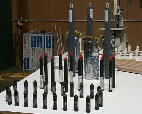
These 43 motors provide 18,805Ns total impulse, which is safely under the California limit of 20,000Ns. (Luckily there is no limit on the number of motors in a single rocket.) As it turns out, the rocket sections resulted in a final weight of 204lbs, plus we will have to add 10-20lbs. of nose weight.
(That's pretty light for a 22' tall rocket of this diameter, eh?) SIMULATIONBelow you can see the side view generated by RockSim once we had entered all the parts of the N1 we were planning to model (other than surface details). This also gave us a weight estimate, although at this point it is a very rough estimate. 
Based on the planned motor selection, RockSim predicted an altitude of 4800 feet, which is most likely a significant overestimate. Our goal is to keep the flight low and easily visible from the ground. 
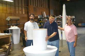
Another significant concern is safety since this rocket has little in the way of fins. It does have some blocks along the side which will provide some fin area, and its basic conical shape also provides some stability. The prototype also had "waffle fins," which moved the C.P. backwards which we will model if possible. However, we will have to add weight to the front to keep the stability reasonable. In the simulation above, the green line indicates stability and you can see the dramatic drop as the stages separate. FOAM CORESThe foam pieces for the body cores arrived on May 17th and you can see how much body there really is in the photo below with the pieces stacked up! 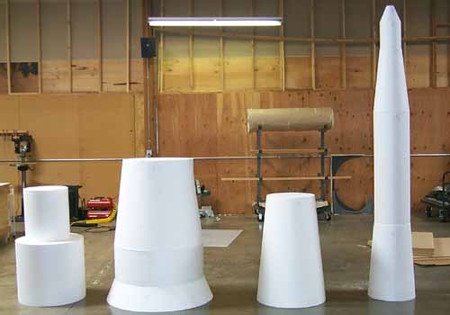
The two pieces in the leftmost stack are the temporary cores for the two interstages. (The open gridwork will be built on a Styrofoam form). Then, from left to right are the three stages. Note that the tower of the third stage is not represented here as it will be turned out of wood. 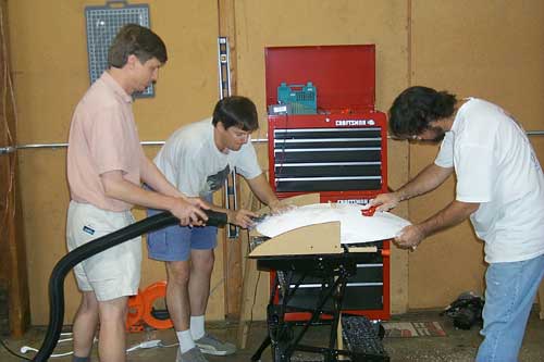
U.S. Foam could not product semi-circular shapes economically and we needed three of them. (One at the base of the booster and one inside each interstage basket.) So, we needed to form the dome shapes ourselves. Nate set up a jig and wire cut the booster dome to rough shape and then we smoothed it out as you can see in the picture above. 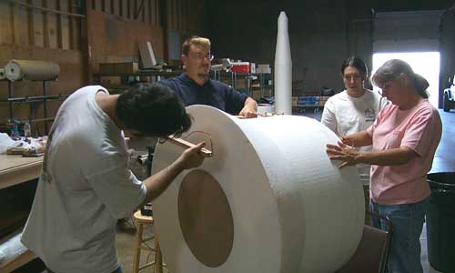
In order to create the core shapes we needed, it was necessary to remove parts of the inside of the foam shapes. We made extensive use of hot wire cutting using a home-made extra large bow. In the picture above, you can see us cutting a large tapered core out of the center of the lower part of the booster for the central motor assembly to fit into. (Sue's daughter Mary Margaret can be seen to her right.) Below left you can see a close-up of Chet guiding the wire along the edge of one disk and Sue is on the other end guiding her side of the wire along the other disk. Below right you can see the tapered core piece being removed.
The observant will note that this is not the complete body of the booster. We previously cut off the base part which had the tapered core and handled it separately. The (top) rest of the booster has a smaller cylindrical core which accomodates the booster recovery system. This involved four pieces of foam for the booster and two large core cut-outs.
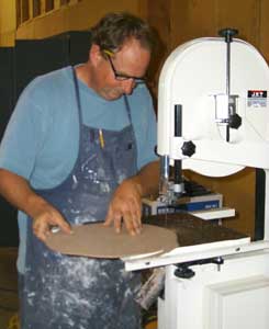
We even true up a few of the cones which were cut out crooked. In the photo above left you can see Bob cutting out one of the many guide disks for hot wiring the foam and above right you can see him preparing to cut out a core from one of the sustainer foam pieces. 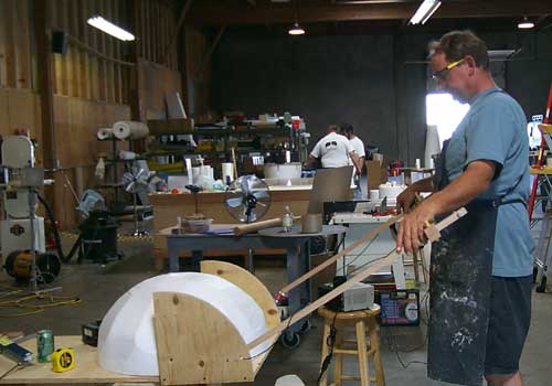
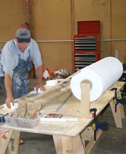
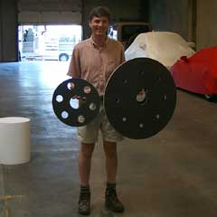
There were also lots of other pieces that we had to make ourselves. In the picture above, you can see Bob forming one of the interstage domes by successively hotwiring in a circle. (Nate made the dome at the base of the booster the same way.) BULKHEADSIn order to avoid the excessive weight of plywood, we created the large bulkheads out of composite using carbon fiber, fiberglass and end-grain balsa cores. The bulkheads were all ½" thick with carbon on the top and bottom and two layers of ¼" balsa core with 6oz. fiberglass in the center.
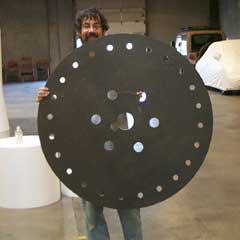
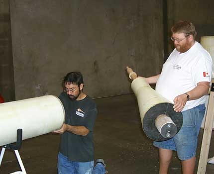
You can see how large the plates ended up being in the photo above. The plate for the aft end of the booster (held by Chet, above left) was 42" in diameter and weighed only 6lbs! Three other plates were also created (held by Chris, above right) for the forward end of the booster motor group, the aft end of the second stage and the aft end of the third stage. 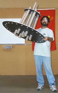
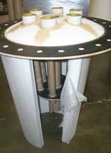
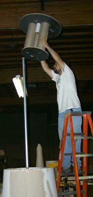
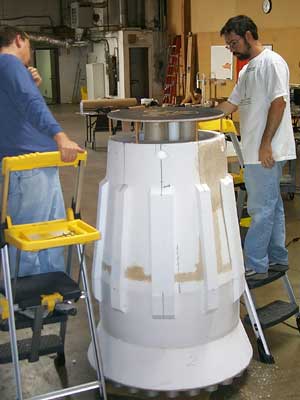
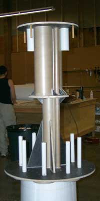
In the photo on the right, you can see the booster base plate with the central motor mount tubes installed (but not yet epoxied in place). (You can see how light the assembly is by how easily Chet can hold it up.) Note that the centeral 3.9" tube helps to create the structure, but will not hold a motor for the L.D.R.S. flight. If you look carefully, you can see the 38mm tube on the side of the central 3.9" tube. This is the internal launch lug. Each stage has a full-length 38mm tube running along the central 3.9" tube which will allow the launch rod to work with a conical rocket. This is an added benefit in that the launch rod is very close to the center of the rocket, reducing the torque from the motors. The holes around the periphery are for the 24 29mm motors (G38s) which simulate the 24 motors in the outer ring on the prototype. Nozzle assemblies will be attached at each of these points and will incorporate the motor mount tubes for the G38s. The motor mount tubes extend down through the base and will penetrate the foam dome which will be attached to the bottom. The central tube will be flush with the bottom of the dome and the tubes in the inner ring will have larger outer tubes which simulate the central motor nozzles and make them look straight. (The 6 motors in the inner ring are canted 1" in 14.4" to point at the estimated C.G.)
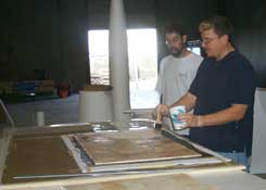
The sequence of photos above shows some steps in the process of making the many composite plates used in the N1. Not shown are the other reinforcements and the second balsa core sheet. The final plates are ½" thick with carbon skins and two ¼" balsa cores with fiberglass in the center. BOOSTERWork on the booster had been going on for a while, but on the weekend of June 30, it really came together. The base plate and motor mount assembly had been built previously and the majority of the booster went together all at once.
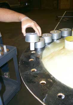
In the pictures above, you can see Sue applying fillets around the central ring of motor nozzles and the complete base ready to be fiberglassed. (We lined the insides of them with Kevlar, which is why you can see a yellow ring in each one.) 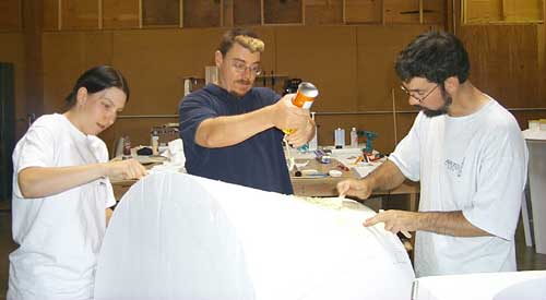
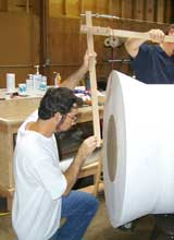
Meanwhile, the rest of us tried to fix a dent in the side of the upper booster section. The company which cut the foam had left a dished out section in the side. In the picture above, you can see me spraying out foam while Chet and Mare smooth it out. 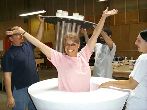
Then we cut out the cores of the booster sections to accomodate the motor mount assembly and the recovery tubes. (See the FOAM CORES section above for more info.) Sue always wanted to jump out of a cake! 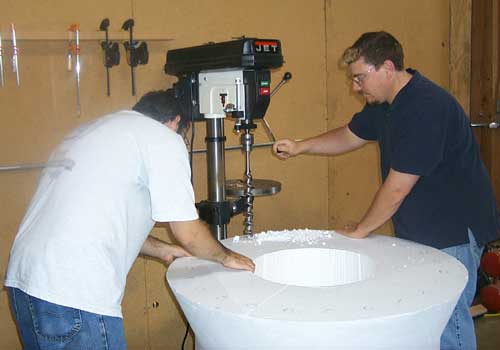
Then it was time to drill the clearance holes for the 24 motor mount tubes in the outer ring. We did this using a large auger bit in the drill press and it worked pretty well. (It certainly removed the foam quickly.) Then it was back to the base plate to cover the foam dome, outside of the nozzles and the outer ring of base plate with fiberglass. We cut squares small rectangles of 6oz. glass cloth and laid them over the surface until it was entirely covered.
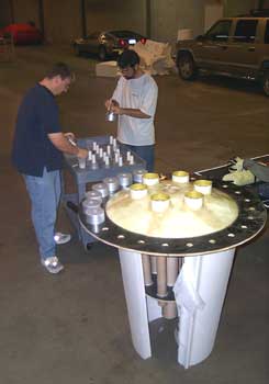
Finally on Saturday night, it was time to trim the excess fiberglass and install the booster nozzles. Everything about this rocket is large and complex and installing 24 MMT/nozzle assemblies at 11:00pm is typical for this project. (We had to get them on before the fiberglass covering the base was fully cured.)
The recovery system for the booster includes three parachute tubes around a central 98mm tube for the interstage basket bridle. It also includes two electronics bays for redundant recovery. This unit was built from two plates with various Loc/Precision tubing installed as you can see in the picture above. 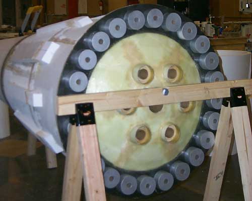
The photo above shows a view of the booster from the bottom. That's an impressive collection of nozzles! You can also see the conduit details made from foam on the sides of the booster. 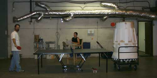
The photo above shows the completed booster, ready for fiberglass. It's even playing a game of ping pong with Chet (although it didn't manage to score any points). Starting on the weekend of July 7, which actually started on Thursday evening, it got to be late night after late night... 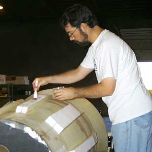
Fiberglassing the booster turned out to be a huge job. Mare and Larry helped out, but Chet did most of the work and hung in there and finished it in a marathon session on Saturday, July 7. This was truly a feat of concentration and commitment. The booster has a huge amount of surface area, plus the conduit detail required extra pieces of fiberglass to be applied over the different surfaces. Also, the pieces of 'glass were so large that they would tend to slip off if they weren't on the top. But, Chet figured out a system. By starting with the troughs between the conduits, letting those pieces partially cure, trimming the excess and then going on to the tops, he was able to get it all together. Then, of course, there were the large sections at the top and bottom of the booster to do! 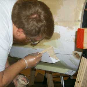
Of course, there was lots of preparatory work to the fiberglassing as well. In the picture on the right, you can see Larry filling gaps in the foam joints with thickened epoxy. There was lots of detail on this rocket. This was such a large project that several people could work on it at once. Larry is filling joints on one side while Chet is fiberglassing the other side. Larry and Mare also jumped in and did a bunch of 'glassing on the booster. Booster fiberglass took much longer than we had expected. It wasn't done until after midnight on Saturday and we were all exhausted. But, the booster really did need a fiberglass skin to protect the foam. 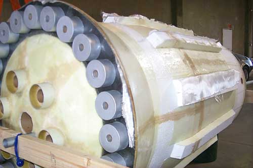
On Sunday morning, Chet wheeled the booster outside and sanded off the sharp edges and stray fiberglass pieces. The booster was now structurally complete! 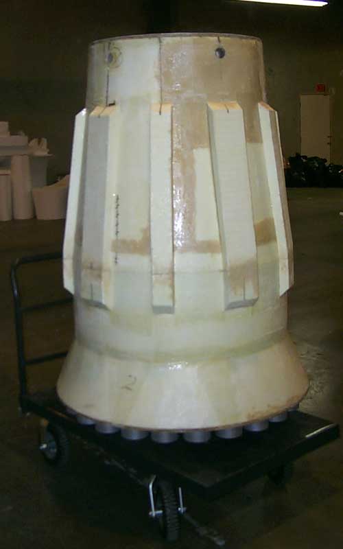
SECOND STAGEThe second stage is more of the same construction. Actually, this is the smallest and simplest of all the stages. The exterior is a single cone.
This stage accomodates two parachutes for recovery and eight motors. The very strange guts of the second stage can be seen above left. Note the motor mount tubes below and the recovery tubes above. (The top plate is just placed here for the photo.) 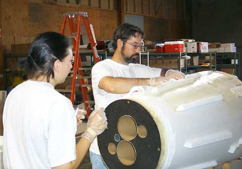
Then, of course, it was time to fiberglass the outside. Chet and Mare did all the fiberglassing on this stage, with Chet starting and Mare finishing. This stage had a large amount of surface detail, which takes a lot of time to fiberglass. SUSTAINERThe sustainer is the longest stage and we decided to break it in half for recovery (not to mention transport). The forward part of the interstage has a bay to accomodate weight, but no electronics or recovery systems. The aft end of the sustainer contains the parachutes for both halves and the staging electronics. Since this is a third stage, we cannot stage with G-Wiz units. Instead, we are flying a Missile Works WRC² wireless remote control. The WRC² has two channels and we will use one for staging and the second for backup recovery system deployment. 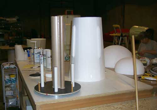
The sustainer also has the launch lug which runs through all stages, but it doesn't go all the way through. In fact, it just goes up into the aft section. In the picture above, you can see the (much simpler) sustainer insides and the bottom cone of the sustainer. 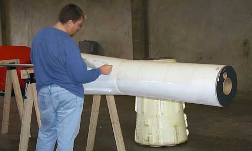
By the time we started to fiberglass, we were happy that this was the last piece! Larry took the forward end of the sustainer home to 'glass. John and Mare glassed the aft end. 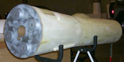
In the picture above, you can see the aft half of the sustainer completed and ready for paint.
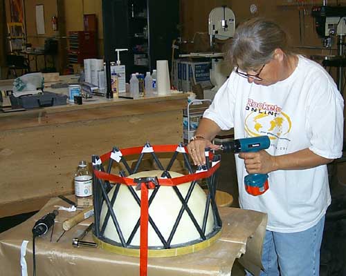
Larry had separately 'glassed the forward part of the sustainer and the test fit happened on Saturday, July 14. Above, you can see Chet and Larry preparing to test fit the two pieces and on the right you can see the entire sustainer together for the first time. INTERSTAGESOne of the more interesting parts of the rocket are the interstages. We decided to model them prototypically with the same trusswork as the real N1 had. Needless to say, this was a lot of work and Sue took it on. 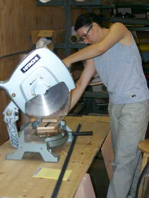
In the picture on the right, you can see Mare cutting the struts for the first interstage out of fiberglass kite spars. Note that each one is cut at an angle and she's using a jig to make sure they are all identical and the angled ends line up. The interstages required a huge amount of planning because they had to mate with the stages above and below, they had to handle the weight of the stages above not to mention that they had to look right. Each interstage required a bottom plate with a "washer" ring cut from the same plate material bonded to it, a center washer and a double thick top washer. All these had to have angled holes which lined up with each other and keyed properly into the two stages they joined. Sue had to bring out the trigonometry on this one. 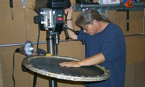
In the picture above, you can see Sue drilling the angles holes in the bottom plate of the first interstage. This interstage had 16 pairs of struts (making 16 'X's). 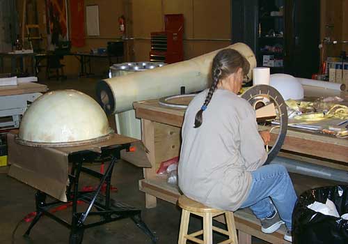
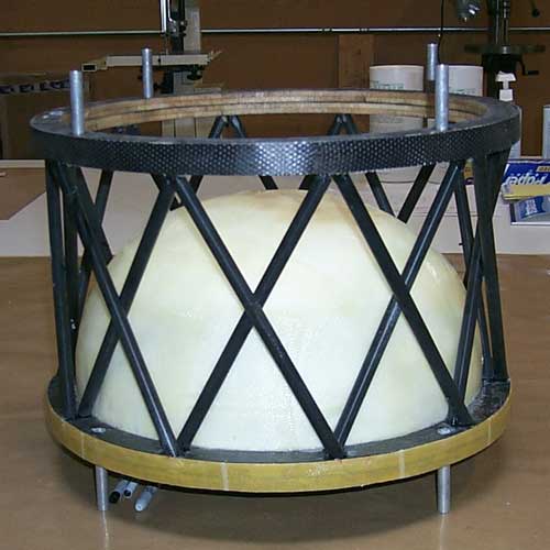
In the picture above you can see sue working on a washer for the first interstage. She spent a lot of time like this! To her left, you can see the first interstage base with dome installed and fiberglassed. 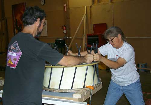
Here you can see Sue and Chet adjusting the first half of the struts so that it ended up making proper X shapes. This took a bit of tweaking since the holes in the balsa plates couldn't be precise enough. 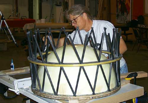
Next, the center ring and the second set of struts were installed. 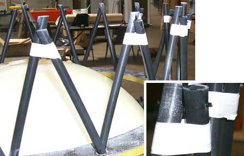
The tops of the struts were pinned together to hold them in place for installation of the top ring. 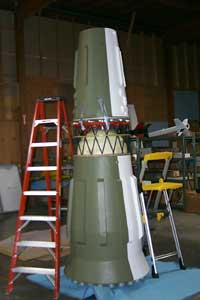
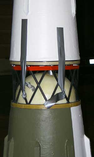
The top ring had to be aligned with the bottom of the second stage and so was drilled last and fit with the stages together. In the photo on the right, you can see the basket between the booster and second stage. 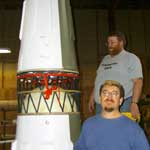
Note that the pins joining the top and bottom of the basket are in place and the central launch lugs are alignd with conduit. Once everything matched up, the top ring was marked and its holes drilled. The second basket went together pretty much like the first. However, we decided to leave out the central ring because it looked too busy. Here are some pictures of the second basket:
These interstages turned out wonderfully and are really the crowning glory to the rocket. The structure here not only looks like the real N1, but supports the weight in the same way! 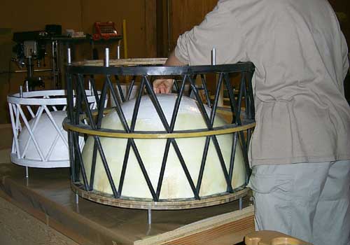
The two interstages were finally completed on Monday, July 16. In the picture above, you can see them as Mare started to paint the larger basket (first interstage). PAINTINGSince Bob is a painting contractor by trade, he led this part of the project. Since there was so much surface area, we decided to use house paints and brush them on. I don't think I've ever brushed paint on a rocket before! Most of the painting was completed on Saturday, July 14. 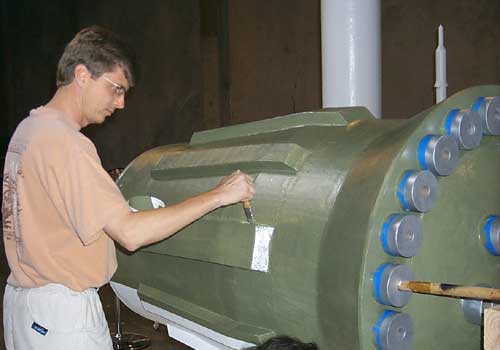
First we painted the entire airframe using a white primer. ("The Gripper," which sticks well to most things.) 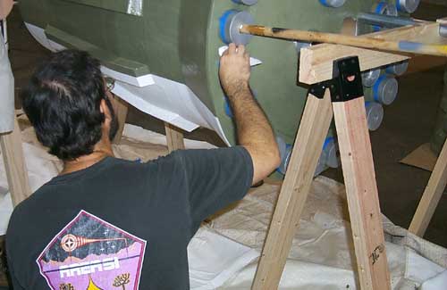
Then, the areas which were green were painted on top of the primer. (The green paint didn't stick well to bare fiberglass as we found out.) 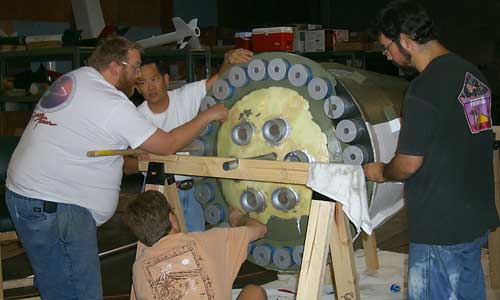
In the picture above, you can see what happens when you paint directly on fiberglass. The green paint literally peeled off in sheets, so we had to peel it all off again. (Pius stopped by to see us in action.) 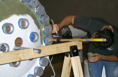
Here you can see Chet repainting the green after the first coat was peeled off and the bottom of the booster was painted first with the primer.
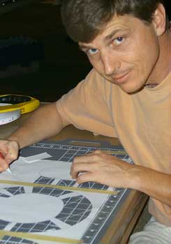
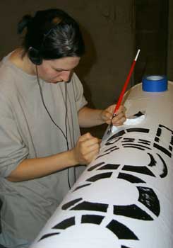
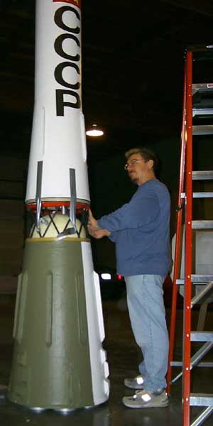
Even though it is not prototypical, we decided to add a flag and "CCCP" to the sustainer. After all, the actual moon shot would have gotten publicity and would have had appropriate decoration. 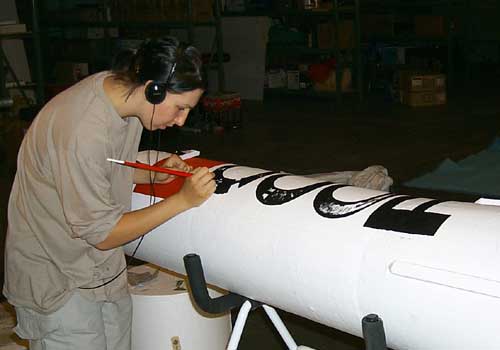
Bob printed out the lettering and Chris cut out a stencil. Then they got the rough outline of the lettering on the sustainer and Mare painted the actual letters. They did the same thing with the Soviet flag logo on the red square. 
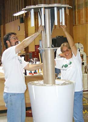
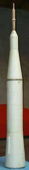
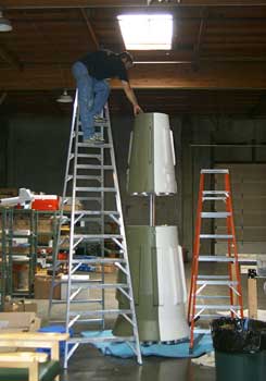
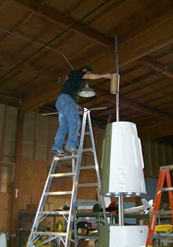
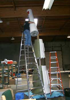
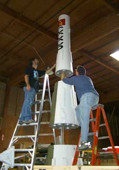
There we go! Now the booster is done. You can also see the other airframe sections painted. (This picture was taken Saturday evening.) On Sunday, we decided to stack up the airframe sections to see how the rocket would look. Unfortunately, the ceiling in the warehouse isn't tall enough for all of the rocket, but we were able to stack up the first and second stages and the aft section of the sustainer.
In the sequence of pictures above, we stacked up the sections with spaces representing the interstages. This rocket involves a lot of work on ladders! 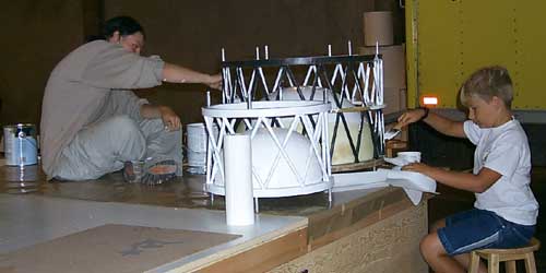
On Monday, July 16 the baskets were ready to paint. Mare and Peter (Sue's son) painted the baskets (although Mare did most of the work). 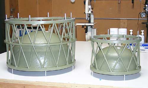
Here the are! These are the last pieces to be completed and now the rocket is ready for LDRS. | ||||||||||||||||||||||||||||||||||||||||||||||||||||
|
||||||||||||||||||||||||||||||||||||||||||||||||||||
 The moon race specifies 1/16 scale rockets, making the N1 model 22 feet tall overall
with the widest part of the rocket (the base) 42" wide!
The rocket will have three stages and fly on 43 motors totalling 18,800Ns total impulse.
The body of the rocket will be built out of foam covered with fiberglass and is estimated
to weight between 125 and 150 lbs.
The moon race specifies 1/16 scale rockets, making the N1 model 22 feet tall overall
with the widest part of the rocket (the base) 42" wide!
The rocket will have three stages and fly on 43 motors totalling 18,800Ns total impulse.
The body of the rocket will be built out of foam covered with fiberglass and is estimated
to weight between 125 and 150 lbs.
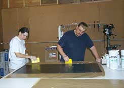 1. Bottom reinforcement is wet out by itself (in this case carbon fiber).
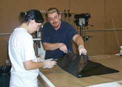 2. Reinforcement is transferred to vacuum bagging area
(onto breather and release already prepared).
2. Reinforcement is transferred to vacuum bagging area
(onto breather and release already prepared).
 3. First balsa core is applied on bottom reinforcement and top is painted
with epoxy.
3. First balsa core is applied on bottom reinforcement and top is painted
with epoxy.
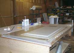 4. Complete lay-up in vacuum bag (we're using a veneer press here).
